Post-processing is the act of transforming the initially generated output into a final output. In this case this means modifying the Color, Depth and Normal buffers as needed after the path tracing step has completed. Post-processing is not required for the ray tracer to work, but can be useful for creating interesting effects.
Important
The post-processing step only runs after the path tracing step has completed. This means that individual path data is not available to post-processing shaders. Unlike path shaders, post-processing shaders have access to all pixels in every buffer at once.
Post-processing shaders
Post-processing shaders are shaders that are run after the path tracing step has completed. They are run on every pixel in the scene, and can modify the Color, Depth and Normal buffers.
Creating a post-processing shader
Let's create a shader that detects edges in the image based the shapes of the objects in the scene. We will be using depth-based edge detection, which isn't the most accurate method, but is simple to implement.
It is recommended that you create a new folder in the Luau Ray Tracer package called postprocessing and put your post-processing shaders in there. For the purposes of this tutorial, we'll be assuming you do that.
Start by creating a new ModuleScript called EdgeDetection in the postprocessing folder.
Depth-based edge detection works by comparing the depth of each pixel to the depths of the adjacent pixels. If the difference between the depths is greater than a threshold, the pixel is considered an edge.
-- Depth difference threshold to detect edges.-- If the depth difference between a pixel and its adjacent pixel is greater than this threshold, the pixel is considered an edge.localedgeThreshold=0.2EdgeDetection.Function=function(Raytracer,...)-- Loop through every pixel in the image.forx=1,Raytracer.Camera.Resolution.Xdofory=1,Raytracer.Camera.Resolution.Ydo-- Get the depth of the current pixel.localCurrentDepth=Raytracer.Buffers.Depth[x][y]-- Collect all the adjacent pixels.-- The first argument is the pixel's position, the second is the size of the ray traced viewport.-- The third argument is the radius of the area to search for adjacent pixels.localAdjacentPixels=EdgeDetection:GetAdjacentPixels(Vector2.new(x,y),Raytracer.Camera.Resolution,1)localAdjacentDepth={}-- Get the depth value for each pixel position from the depth bufferfor_,pixelinAdjacentPixelsdotable.insert(AdjacentDepth,Raytracer.Buffers.Depth[pixel.X][pixel.Y])end-- Sort the depths. We'll use this to find the minimum and maximum depths.table.sort(AdjacentDepth)-- Get the difference between the depths.localDepthDifference=math.abs(AdjacentDepth[1]-AdjacentDepth[#AdjacentDepth])-- If the difference is greater than a threshold, the pixel is an edge.ifDepthDifference>edgeThresholdthen-- Edges will be highlighted in red in the image.-- Note that SetPixel sets the color of the pixel, not the depth.Raytracer:SetPixel(x,y,Color3.new(1,0,0))endendend-- Since we don't need to generate any more buffers, we can return the Ray Tracer's buffers in their current state.-- This has the same result as returning nil.returnRaytracer.BuffersendreturnEdgeDetection
-- ModuleScriptlocalPostProcessingShader=require(script.Parent.Parent.classes.PostProcessingShader)localEdgeDetection=PostProcessingShader.new()-- Depth difference threshold to detect edges.-- If the depth difference between a pixel and its adjacent pixel is greater than this threshold, the pixel is considered an edge.localedgeThreshold=0.2EdgeDetection.Function=function(Raytracer,...)-- Loop through every pixel in the image.forx=1,Raytracer.Camera.Resolution.Xdofory=1,Raytracer.Camera.Resolution.Ydo-- Get the depth of the current pixel.localCurrentDepth=Raytracer.Buffers.Depth[x][y]-- Collect all the adjacent pixels.-- The first argument is the pixel's position, the second is the size of the ray traced viewport.-- The third argument is the radius of the area to search for adjacent pixels.localAdjacentPixels=EdgeDetection:GetAdjacentPixels(Vector2.new(x,y),Raytracer.Camera.Resolution,1)localAdjacentDepth={}-- Get the depth value for each pixel position from the depth bufferfor_,pixelinAdjacentPixelsdotable.insert(AdjacentDepth,Raytracer.Buffers.Depth[pixel.X][pixel.Y])end-- Sort the depths. We'll use this to find the minimum and maximum depths.table.sort(AdjacentDepth)-- Get the difference between the depths.localDepthDifference=math.abs(AdjacentDepth[1]-AdjacentDepth[#AdjacentDepth])-- If the difference is greater than a threshold, the pixel is an edge.ifDepthDifference>edgeThresholdthen-- Edges will be highlighted in red in the image.-- Note that SetPixel sets the color of the pixel, not the depth.Raytracer:SetPixel(x,y,Color3.new(1,0,0))endendend-- Since we don't need to generate any more buffers, we can return the Ray Tracer's buffers in their current state.-- This has the same result as returning nil.returnRaytracer.BuffersendreturnEdgeDetection
Important
Note that the Function property of the shader is a function that takes the Ray Tracer as its first argument. This is passed automatically when calling RayTracer:PostProcess(). ... is the rest of the arguments passed to the shader via the RayTracer:PostProcess method.
Important
The shader function is responsible for selecting the appropriate pixels to modify. If you want to modify every pixel in the image, you can do so by looping through every pixel in the image, as seen in the code above.
Note
The post-processing shaders are expected to return nothing or the Ray Tracer's buffers to be used for the next post-processing shader. If the shader returns nil, the Ray Tracer will continue to use its current buffers. Returning the buffers can be useful if you want to pass additional information to the next post-processing shader, as you can return more buffers than what the Ray Tracer has by default.
Now let's add the Edge Detection shader to our main script.
Just like the other shaders, post-processing shaders are passed to the Ray Tracer in a table and executed in order.
If we try rendering our scene again, we'll notice that nothing has changed. This is because post-processing shaders are not automatically executed when rendering a scene.
To execute the post-processing shaders, we can call the RayTracer:PostProcess() method after the initial render:
localRayTracingCamera=require(package.classes.RayTracingCamera)localRayTracer=require(package.classes.RayTracer)localTestShader=require(package.shaders.TestShader)localSkyShader=require(package.shaders.SkyShader)localEdgeDetection=require(package.postprocessing.EdgeDetection)-- We'll use a resolution of 100x100 to avoid having to wait too long for the render to complete.localresolution=Vector2.new(100,100)localfieldOfView=math.rad(70)-- Field of view is measured in radians.localnearPlane=0.1-- The near plane determines how close the camera can be to an object before it is clipped.localfarPlane=100-- How far the camera can see.-- We'll place the camera 5 studs above the world origin.-- Because we're not defining a direction, the camera will be looking down the -Z axis.localCFrame=CFrame.new(Vector3.new(0,5,0))-- Create the camera.localmyCamera=RayTracingCamera.new(resolution,fieldOfView,nearPlane,farPlane,CFrame)-- We won't be defining shaders just yet, so we don't need to pass any parameters except the camera.localmyRayTracer=RayTracer.new(myCamera,1,{SkyShader,TestShader},{EdgeDetection})localimage=myRayTracer:Render()myRayTracer:PostProcess()functionshowImage(image)forx=1,#imagedofory=1,#image[x]dolocalpixel=Instance.new("Part")pixel.Size=Vector3.new(1,1,0)pixel.Position=Vector3.new(x,resolution.Y-y,-resolution.X)-Vector3.new(resolution.X/2,resolution.Y/2,0)pixel.Anchored=truepixel.CanCollide=falsepixel.CanTouch=falsepixel.CanQuery=falsepixel.CastShadow=falsepixel.Locked=truepixel.Color=image[x][y]pixel.Material=Enum.Material.SmoothPlasticpixel.Parent=workspaceendendendshowImage(image)
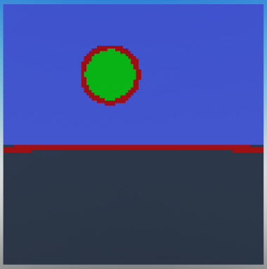
Now let's try rendering our scene again.
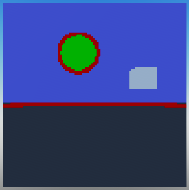
That looks pretty good! Let's try adding some more parts to the scene.
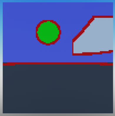
Looks like the white block's edges are not detected. This is because in this particular example it's located close to the camera's far plane, resulting in the depth difference between the block and the camera to be too small for our shader to detect. In our shader we set 0.2 as the threshold, so an edge's minimum depth difference is 20% of the camera's far plane distance. In our main script we set the far plane to 100 studs, so the minimum depth difference is 0.2 * 100 = 20. Therefore, if the object is more than 80 studs away from the camera, it won't be detected as an edge.